Process
When I started with this assignment, I had absolutely no idea which material I would use for the LoFi prototype. After some feedback from the teacher, I settled on LEGO. I should also note that even though the prototype is made from LEGO, that does not mean LEGO already has this idea or sells it. I only used the material as a fast way to build and iterate. LEGO is also a very "self-guiding" material (the studs basically teach you how to connect parts), which makes it useful for quick prototyping and trying out ideas without overplanning. This also matches the idea from Invent to Learn that I should get to a first prototype quickly so I can check assumptions and improve through iteration, instead of getting stuck in planning.
Technical hurdle
I wanted to make more out of the prototype, but after spending hours sifting through the LEGO pieces I had, I ended up with a simpler design: one base hub and two modules (see Figure 1). It still gets the idea across, but it did limit how "complete" the system looks.For the magnetic connection system, I used pins that stick out and go into a hollow block. The idea was: easy connect, easy disconnect, without a hard click. I did try using tighter LEGO pins (black/blue ones), but that made the modules click too strongly, and it was hard to unclick them. Since my original concept was closer to a magnetic feel (similar to littleBits), I intentionally went for a looser click/slide connection instead.
Fabrication steps
To make the LoFi prototype, I translated the concept into a sequence of quick fabrication steps instead of trying to build everything at once.
1. Reduce the concept to a testable core
Instead of trying to fabricate the full hub system, I reduced the idea to the smallest version that could still test the interaction: one base hub and two modules.
2. Choose a material that supports rapid iteration
I selected LEGO because it allowed me to build, change, and rebuild the prototype quickly. This matches the iterative prototyping logic from Invent to Learn: get to a first prototype fast, then improve through feedback instead of overplanning.
3. Build the base hub first
I first made the "anchor" piece that represents the main hub. This let me define the scale, connection direction, and placement of the visible ports and indicators.
4. Prototype the connection system
After that, I focused on the most important interaction: how modules attach and detach. I tried different LEGO pin combinations to find a connection that felt stable enough to hold, but still easy enough to remove.
5. Build two modules with the same logic
Once the connection principle worked reasonably well, I made the USB module and the Ethernet module using the same attachment logic. This allowed me to test whether the system still felt consistent when more than one block was involved.
6. Test by handling rather than only looking
Finally, I tested the prototype by physically attaching, removing, reordering, and lifting the modules. Even though the prototype does not function electronically, it still works as a prototype for the user interaction and the modular logic.
This step-by-step fabrication process made the concept tangible, which is important because, as the slides also suggest, a concept on screen can only be discussed, while a LoFi prototype on the table can actually be imagined and handled.
Figure 1. My bedroom while working on the assignment.
Context
Figure 2 and 3 & Video 1 - Overview
These figures show the hub, the modules, and how they connect. The video shows the connection in action. Because the design is modular, the order of connecting modules should not matter: the user can choose which module(s) they want and in what sequence.
Try-out / quick test (LoFi)
Even though the prototype cannot transfer real power/data, I could still test the interaction (what you actually do with your hands):
- whether it is clear where modules should attach,
- whether connecting/disconnecting feels "light" enough,
- whether the modules stay attached when you pick up and move the hub, and
- whether swapping the order of modules still "works" as a concept.
This kind of early feedback-through-doing is exactly why rapid prototyping is useful. You learn faster once you have something physical to handle (and it makes iterating feel much easier, because you can change it right away).
Iteration steps and criteria
While fabricating the prototype, I went through several small but important iterations.
Iteration A - Tight pin connection
At first, I tried tighter LEGO pins (for example, the black/blue friction pins). These made the modules click together securely, but the connection was too strong. It no longer matched the intended "magnetic" feel of the original concept, because disconnecting became annoying rather than easy.
Iteration B - Looser slide/click connection
I then switched to a looser connection using protruding pieces and hollow connector blocks. This was less realistic in a mechanical sense, but much better for testing the intended interaction: quick attach, quick detach, and low effort to rearrange.
Iteration C - Simplified pin layout
My original concept had a more elaborate separation between data and power pins. Because I did not have the exact LEGO pieces I wanted, I simplified that layout in the prototype. This reduced realism, but still preserved the main design idea that there is a repeated connector interface between blocks.
I evaluated these iterations using four criteria:
1. Attachment clarity: Is it obvious where modules should connect?
2. Connection feel: Is connecting/disconnecting light enough?
3. Stability: Do modules stay attached during handling?
4. Reorderability: Does the concept still work when the order changes?
This made the prototype more than a visual model. It became the first physical test of the modular behaviour of the system.
Figure 4, 5, 6, and 7 - Base hub
I started by creating the main hub. The back and side of the hub hold (Figure 6):
- the cable to the laptop on the right side (black rope),
- an extra power input (black chain),
- and a possible internet module at the back.
On the front (Figure 4), I indicated ports/slots: two USB-C (two green pieces), one micro-SD (small grey piece), and one SD card (bigger dark grey piece). I also added a connection light (red piece) to indicate whether the hub is "working," and a screen on top for information (red plate). Having visible feedback is important in making systems easier to understand and "read" while using them.
The connection is done by two one-block extensions (Figure 7), with data/power pins in the middle (I couldn't find the full set of pins I had in mind, so this is simplified).
Figure 8, 9, 10, and 11 - USB module
The second block I made was the USB module. I started with the connection system: since the base hub has extended pins (Figure 7), the module needed a connection that doesn't lock too strongly. After trying different methods (including hard pins), I ended up using hollow 1x1 pieces that slide/click onto the extended part (best seen in Figure 9 and Video 1). This gave the module a more "magnet-like" feel (stable enough to hold, but not so tight that disconnecting becomes annoying).
Figure 12, 13, 14, and 15 - Ethernet module
This module works the same as the USB module in design and connection system (see Figures 13 and 15). Since I cannot make real connections or ports with the LEGO pieces I had, I used a hollow blue block to indicate an Ethernet port (Figure 12). This keeps the prototype focused on the modular idea and the user interaction, instead of pretending the electronics are already solved.
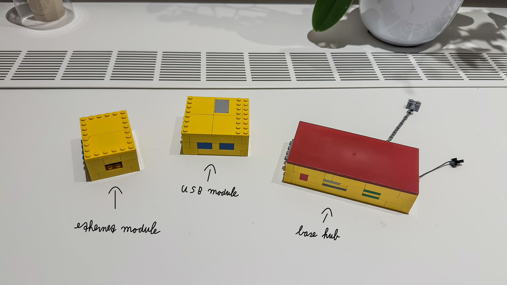
Figure 2. Overall view of the individual hub and modules.
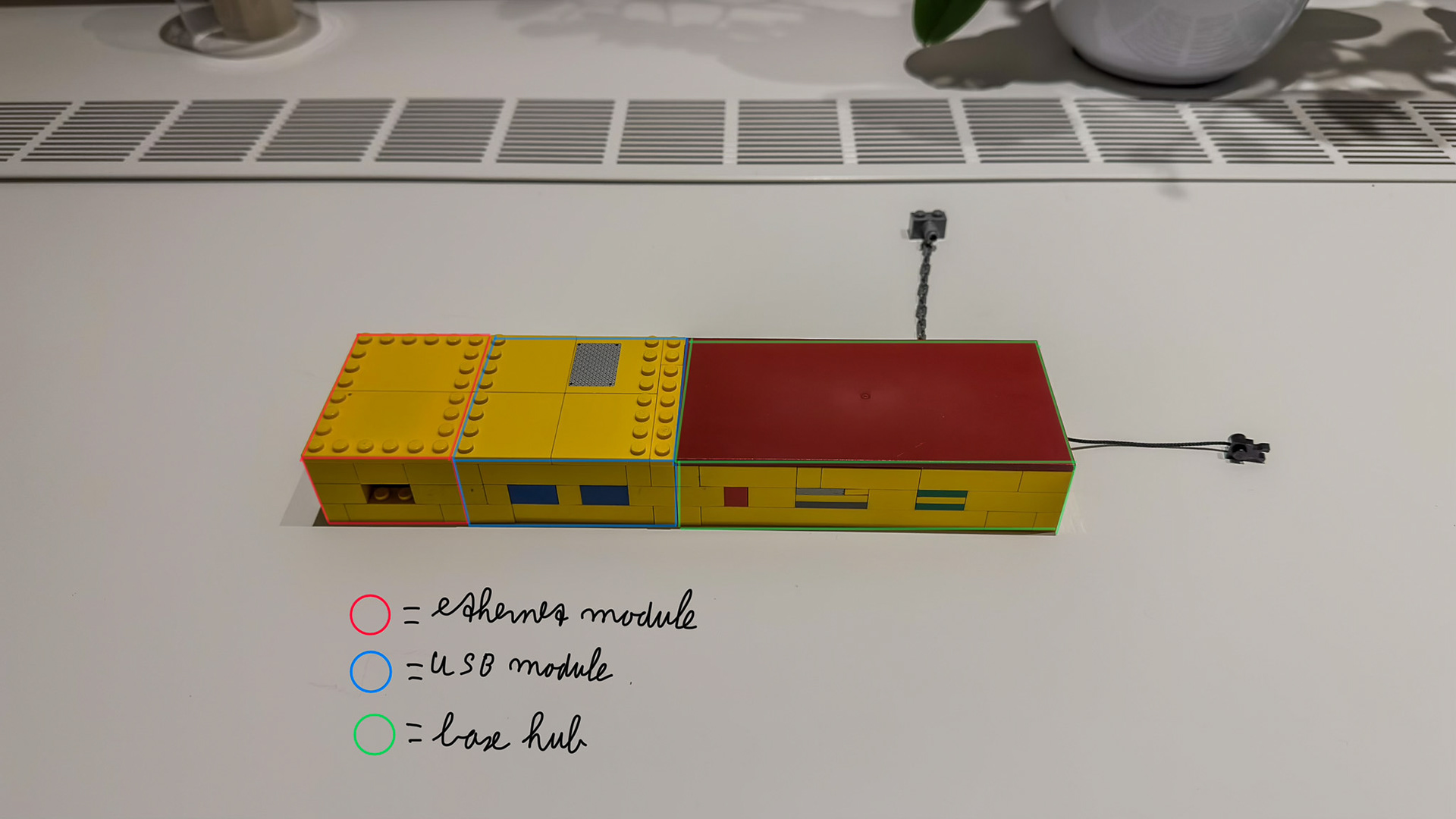
Figure 3. Overall view of the connected hub and modules.
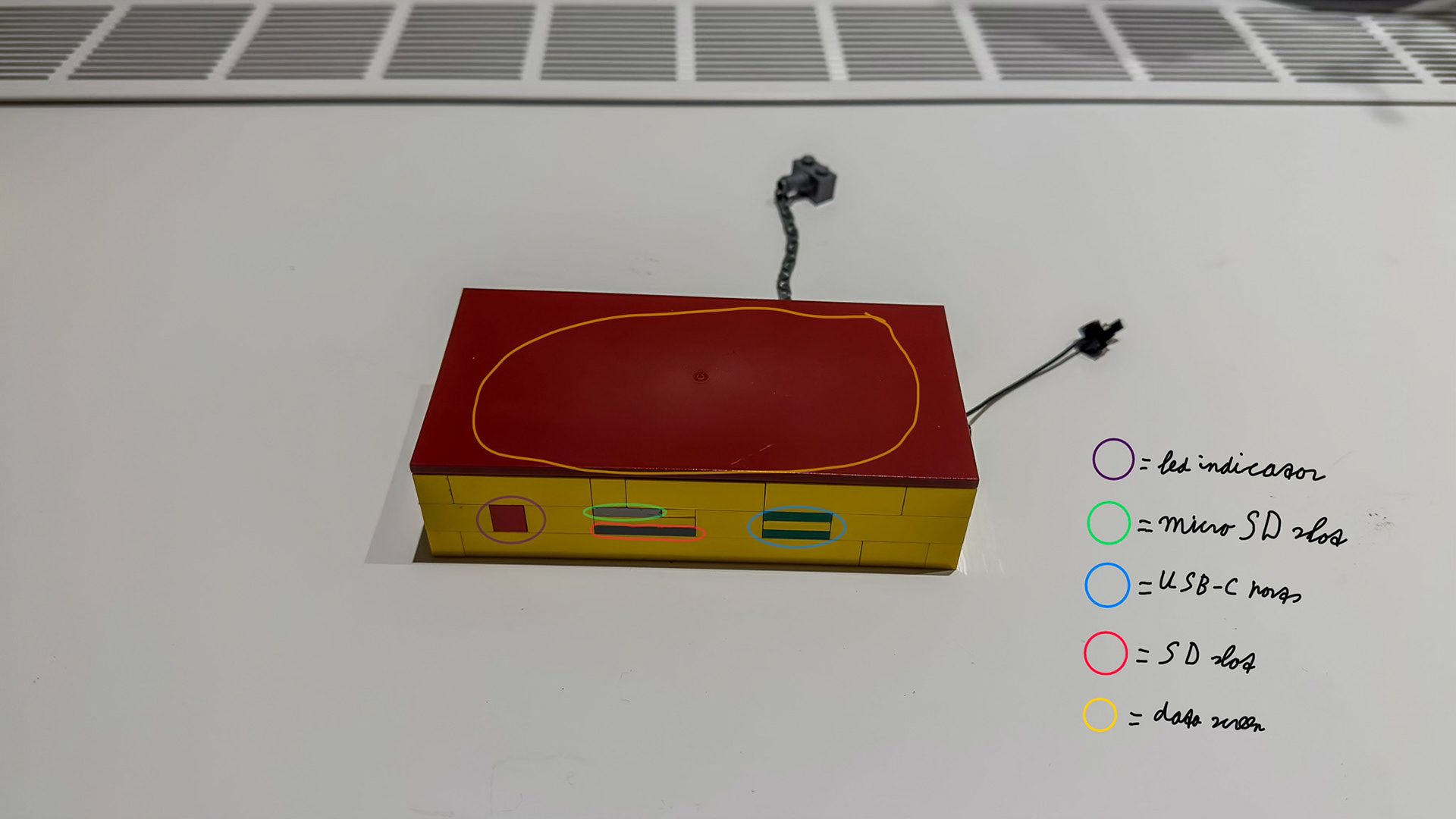
Figure 4. The base hub (front).
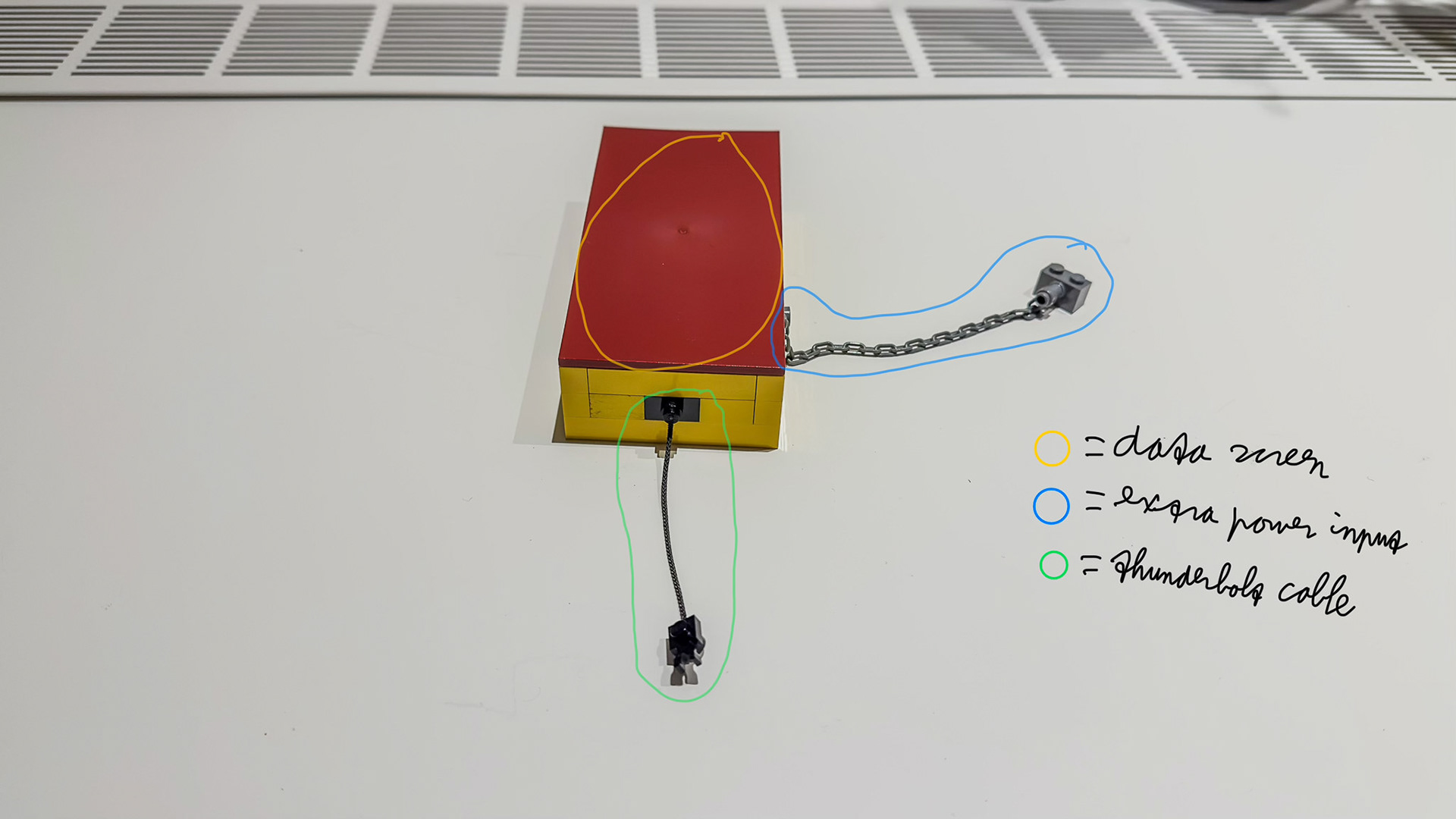
Figure 5. The base hub (right).
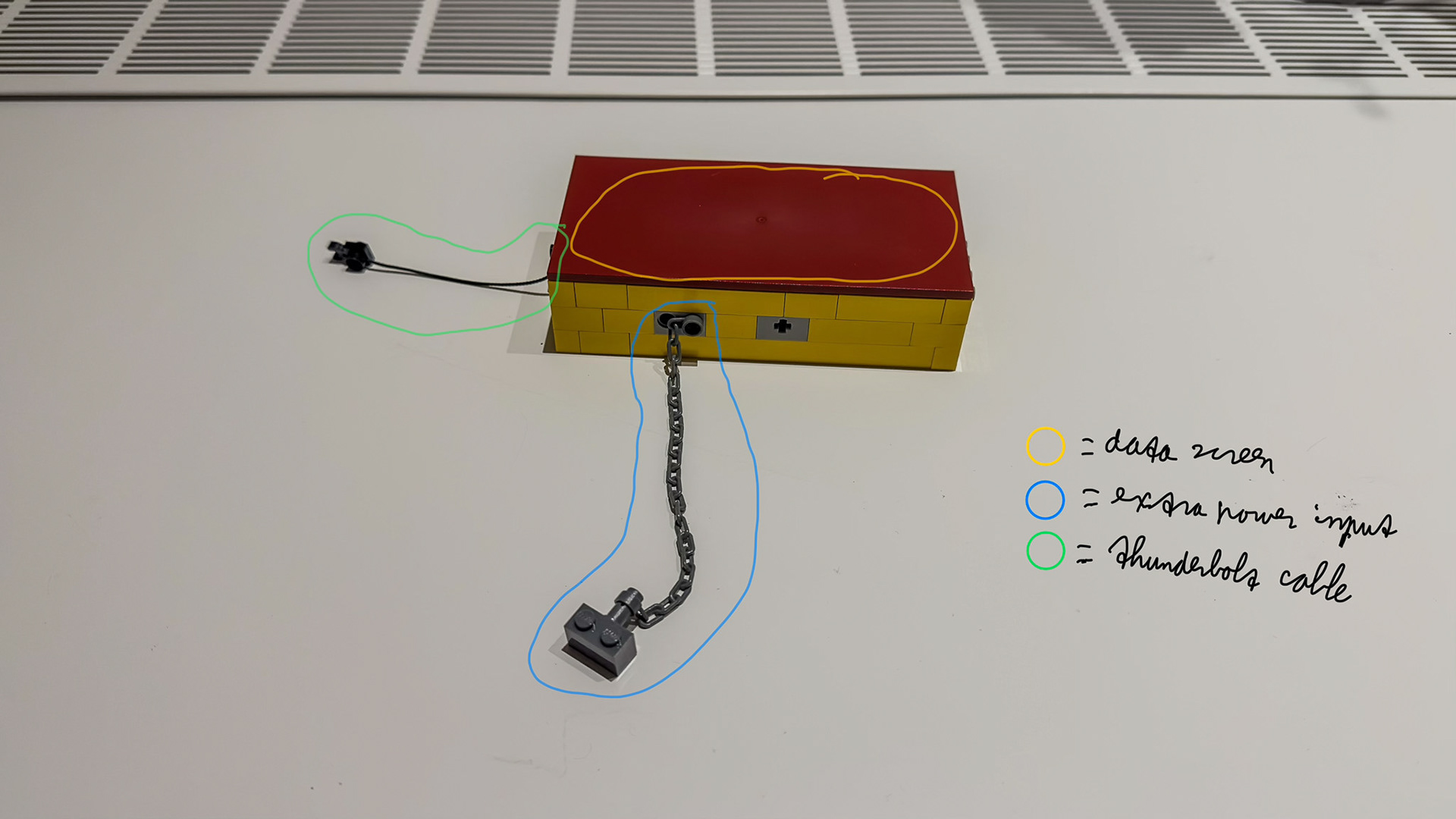
Figure 6. The base hub (back).
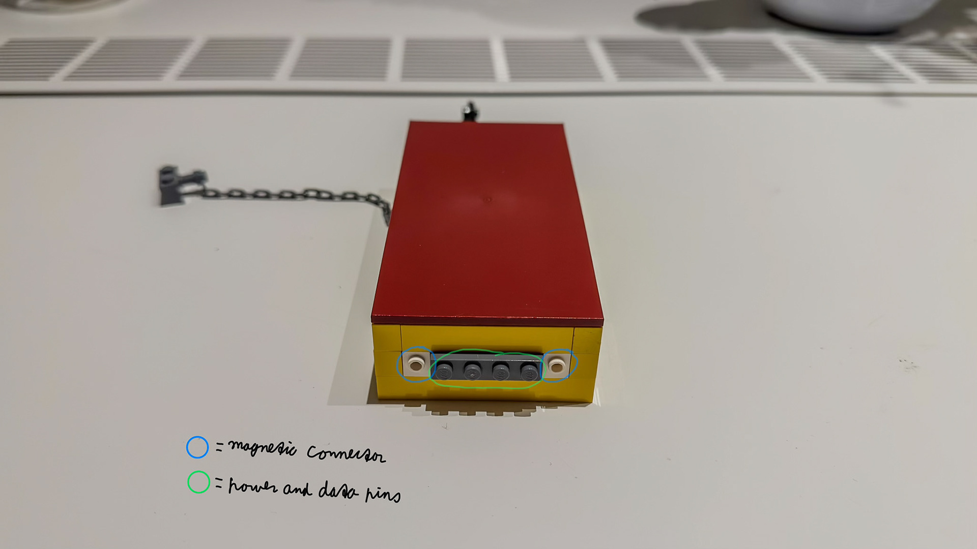
Figure 7. The base hub (left).
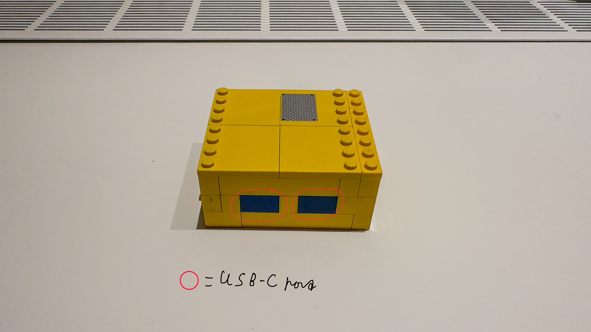
Figure 8. The USB module (front).

Figure 9. The USB module (right).
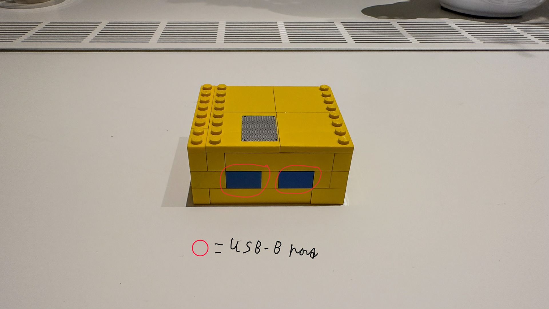
Figure 10. The USB module (back).
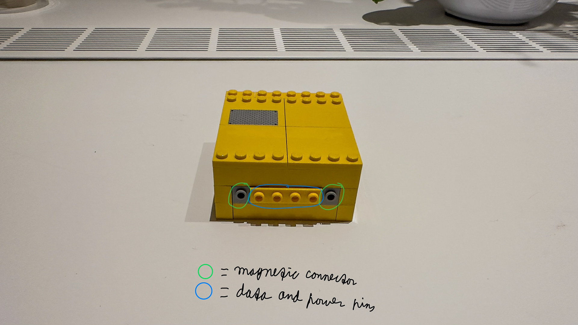
Figure 11. The USB module (left).
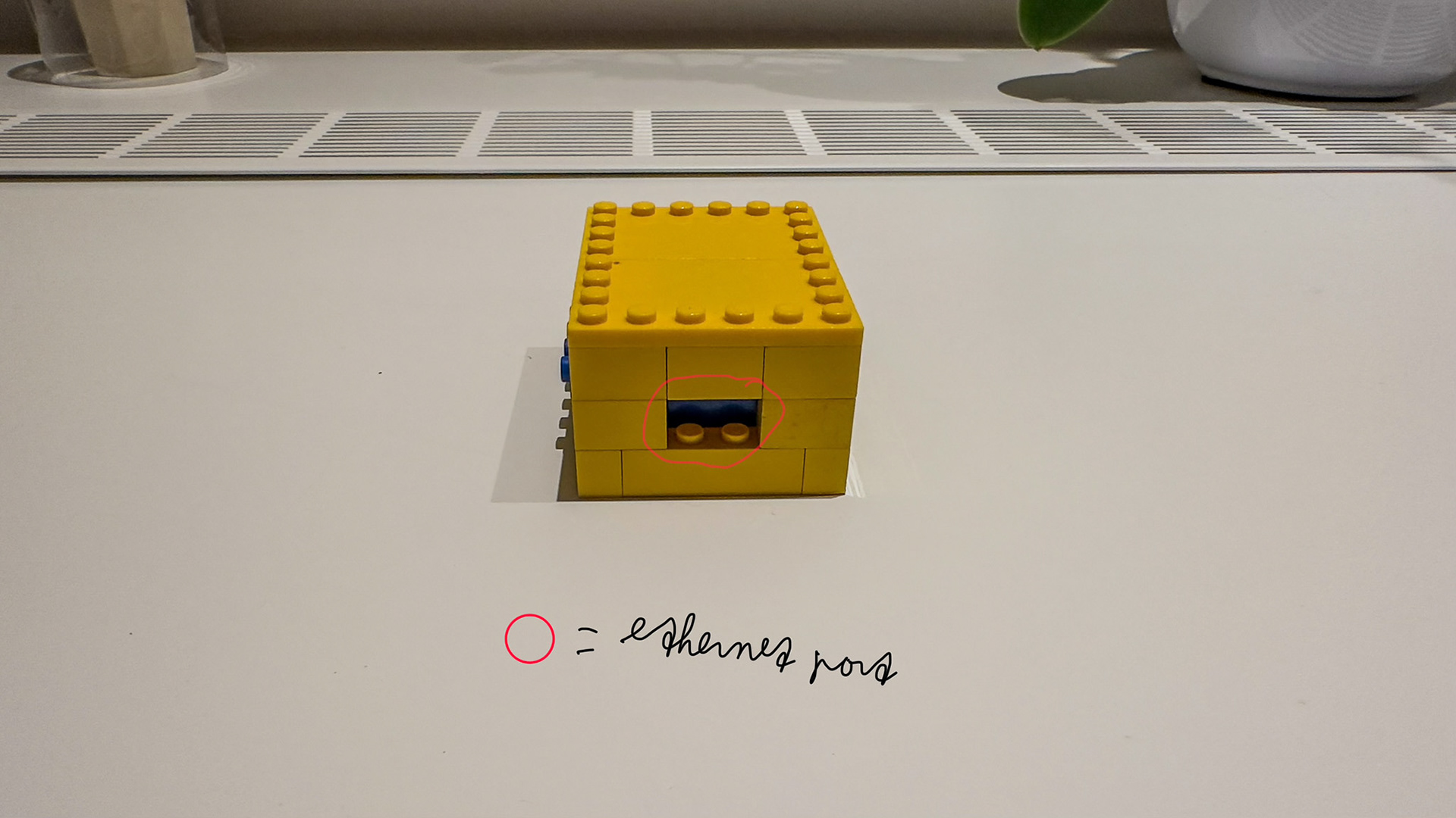
Figure 12. The ethernet module (front).
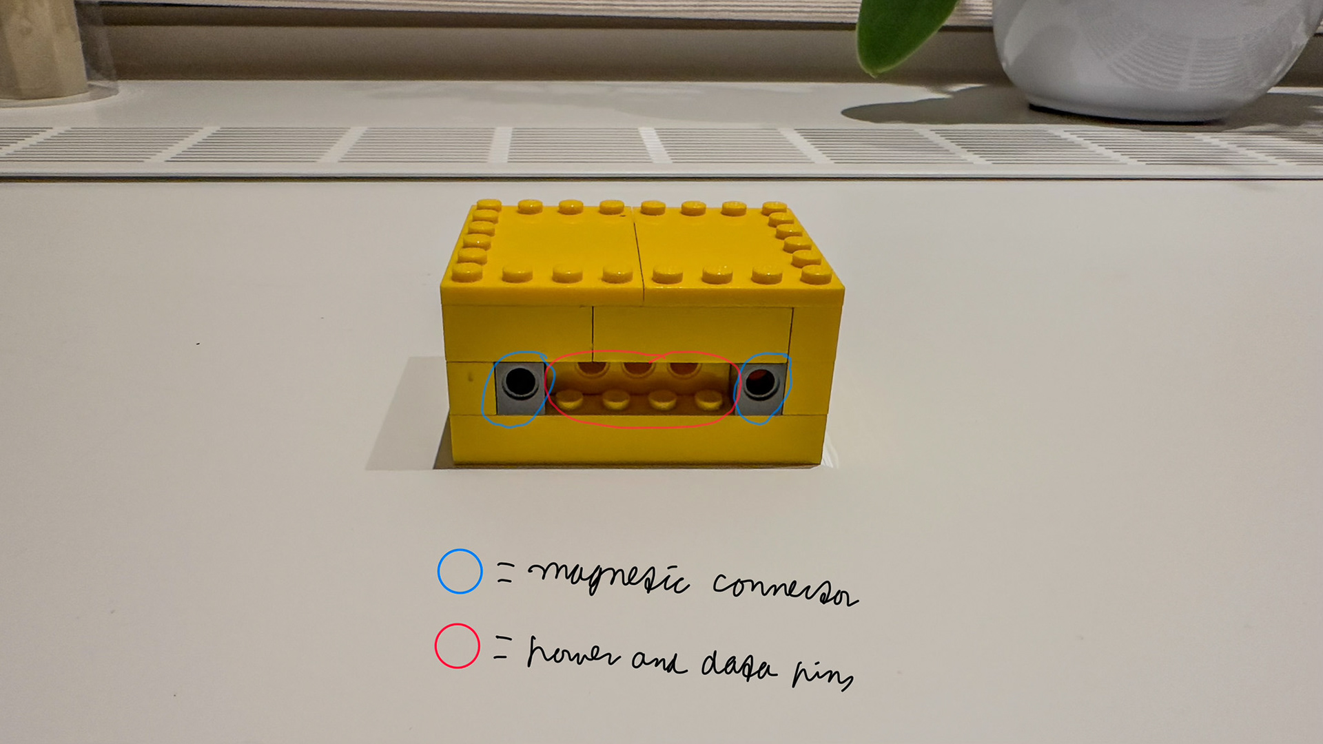
Figure 13. The ethernet module (right).
Figure 14. The ethernet module (back).
